
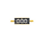
TRS-450 Transmit/Receive Switch & Rx Interface
149,00 €
TRS-450
Transmit/Receive Switch & Rx Interface – Built & Tested Module Encased in Aluminum Box
Available on backorder
This unit allows the insertion of external RF components such as preselector filters, low-noise amplifiers (LNAs), attenuators, notch filters, limiters, or any other circuitry into the receive signal path only, without modifying the internal structure of the transceiver. It also enables the use of different antennas for transmit and receive, different radios for transmitting and receiving, or the integration of an external SDR receiver alongside the main transceiver.
The design incorporates a Transmit/Receive (TR) switch implemented with high-power relays and PIN-diode switching, ensuring effective receiver protection during transmission.
The switching is controlled by the transceiver’s PTT (Push-To-Talk) signal, with optional RF sensing for automatic operation.
The unit operates over a frequency range of DC to 150 MHz.
Functional Description
In conventional transceivers, inserting a preselector filter, LNA, or other receive-only circuitry typically requires opening the radio enclosure, locating the internal receive path, installing relays and coaxial wiring, and modifying the chassis to accommodate additional connectors—an invasive and undesirable process for most operators.
This project eliminates the need for internal modifications by inserting a TR switching interface in series between the transceiver’s antenna port and the external antenna. In addition to the standard antenna path, two auxiliary ports are provided:
RCVR – receiver input/output port
Rx ANT – receive-side antenna port
During transmit mode, the unit directly connects the transceiver to the antenna through high-power relays, preserving the original RF path.
During receive mode, the transceiver’s antenna connector is routed to the RCVR port, while the antenna coaxial cable is routed to the Rx ANT port. This configuration allows external circuitry to be placed exclusively in the receive path.
Any required receive-only devices—such as LNAs, preselectors, notch filters, overvoltage protection circuits, limiters, or noise-generation or analysis equipment—may be installed between the RCVR and Rx ANT connectors. When no external circuitry is in use, these ports must be connected with a short coaxial jumper.
PTT Control and Power Handling
Switching is controlled by the transceiver’s PTT control line, commonly available on a rear-panel accessory connector and typically used to key external power amplifiers.
If an external power amplifier is used, the PTT line may be shared between the amplifier and this TR interface. However, it is critical that the TR unit be installed between the transceiver and the power amplifier, and not between the amplifier and the antenna, as the power handling capability of the unit is limited to:
< 1500 W at HF
< 50 W at VHF
Advanced Operating Configurations
The additional ports enable several advanced operating modes:
Separate Transmit and Receive Radios
The same antenna feed can be shared between a transmitter and a separate receiver. The transmitter is connected to the Transceiver port, while the external receiver is connected to the Rx ANT port. When transmission ceases, the antenna is automatically routed to the receiver.
Separate Transmit and Receive Antennas
A dedicated transmit antenna may be connected to the ANTENNA port, while a separate receive antenna is connected to the RCVR port.
If the receive antenna or its preamplifier requires DC power via the coaxial cable (Bias-T), enabling Jumper 2 supplies 13.8 V DC at up to 250 mA to the remote device.
External SDR or Receiver Comparison
For panadapter operation or simultaneous receiver comparison, the receive signal may be split using an external RF power splitter.
The splitter’s sum port is connected to the Rx ANT connector, with its outputs feeding the transceiver’s RCVR port and an external SDR or receiver.
Note: The RF power splitter is not included in this design and must be sourced separately.